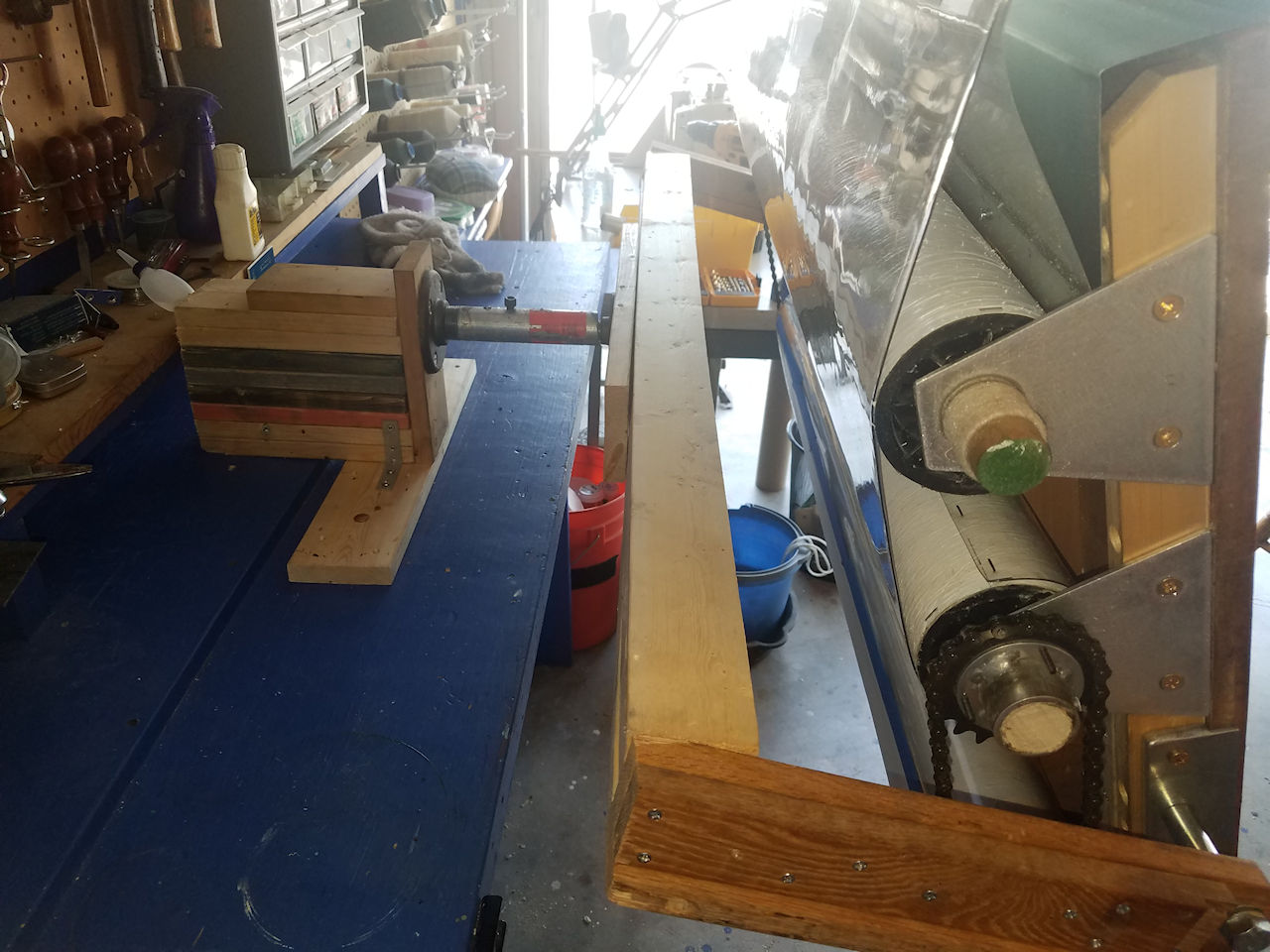
A Large Sheet of Paper, 50" x 38"
Photos 1 and 2, shows the paper attached to a large chipboard that is attached to the drafting table. You'll see it's a pretty tall piece of paper (38 in. x 50 in.). The table is 41.5 inches by 30.5 inches. I tried using the large chipboard, but it's too tall for me to be working on. Photo 3, shows me next to the chipboard and drafting table setup. Thus, I had to draft up something better.

Photo 2: Paper in Garage

Photo 1: Paper under Garage Door

Photo 3: AJ Next to paper on Easel
Drafting Drafting Table Modifications, June 2018
I drafted up modifications for the drafting table to handle the large sheet. Most everything had to be fabricated. I found a machine shop that was suited for doing the work I needed. The six sheets of drafting work are shown below (PDF here). There are some modifications to the work that was done during the fabrication, which I didn't red-line back in, but you'll probably notice them in the final photos. I didn't draft up the arm that attach the table to the workbench I did that from materials left over from the originals table stand and some scrap lumber. Images of those are in the final photos.


Final Photos
The set of Photos from the construction process and the Final Photos are all below.
 Photo-01: I got several chipboard spindles from a local reproduction shop (Academy Repro Prints). They are the spindles that come in the large rolls of paper they print from. |
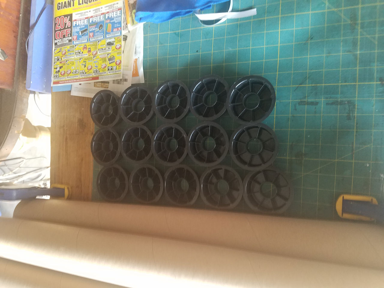 Photo-02: They also gave me the end caps for the spindles. A 1" rod fits perfectly though the end-caps. The length of the spindles was not enough for the width of the drafting table. I got enough spindles to use two for each roller I needed. Each spindle is 36" in length and 3.25 inch diameter. The End caps add about 1/8 inch to the overall length. I'll use a 1.25 inch narrow staple to attach the end cap to the wooden rod at both ends. |
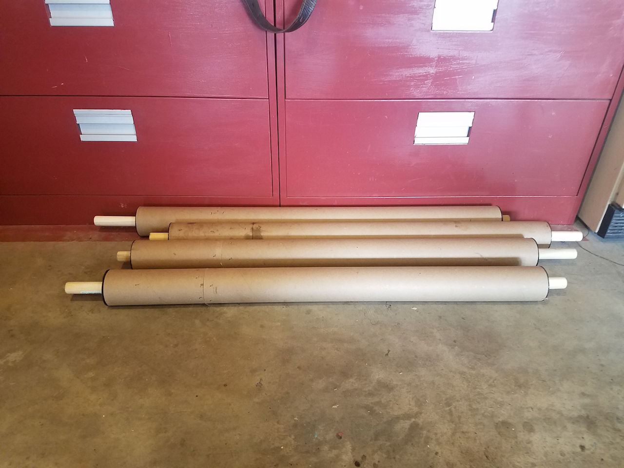 Photo-03: I cut four spindles to 32.25 inches and saved the scrap ring. I cut one spindle into 9 inch sections for the four 32.25 inch spindles I cut a 1.5 inch or so section out of the scrap rings so they could be squeezed into the inside of the spindles and used to attach them together. I added glue to the ring and once the two pieces were together, I shot 2 inch staples into the joint with a pneumatic. I let them set over night. I sanded the spindles to rough them up for a coat of White FlexSeal (liquid for paint brush and rollers). One coat was enough. |
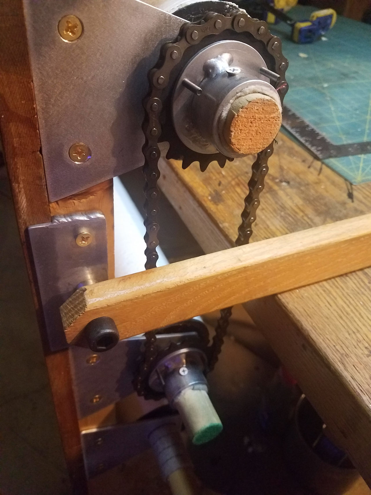
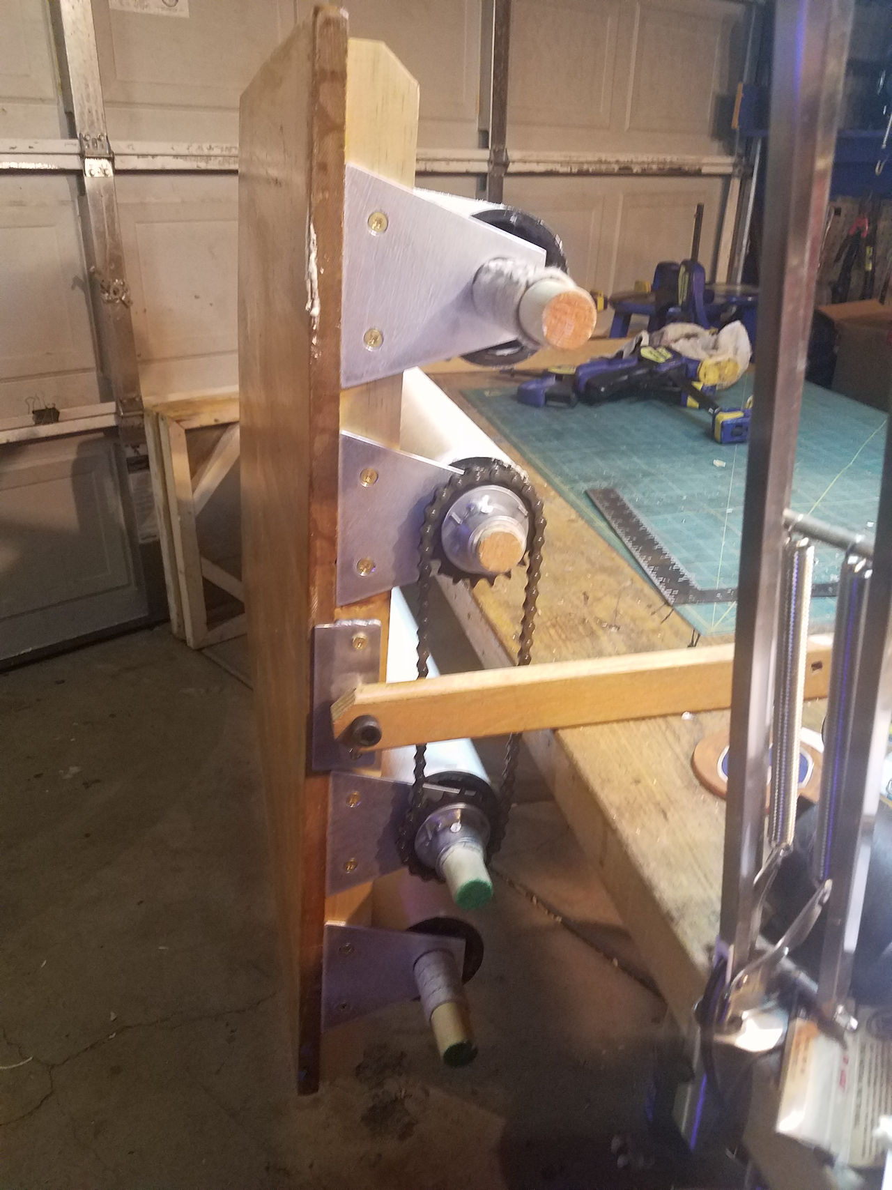 Photo-04: This the following items installed, all the mounting brackets for the spindles, the table mount bracket with a oak brace arm resting on the work table, and the gear assemble with chain on the two inside rollers. The wooden rods have not been cut at this time. |
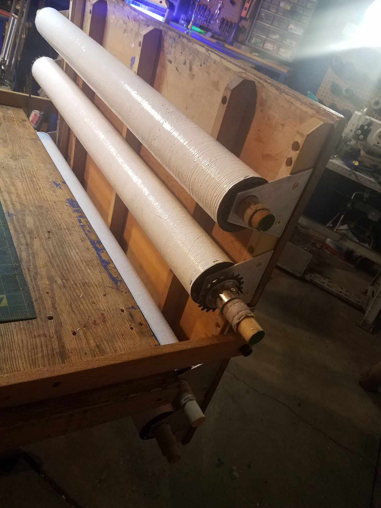 Photo -05: The back view shows the rollers with the white FlexSeal. The shop still has one set of gear assembles, so it is absent in this photo. |
W.R. Mechanical (3709 High St NE, Albuquerque, NM 87107) Provided machine shop services. |
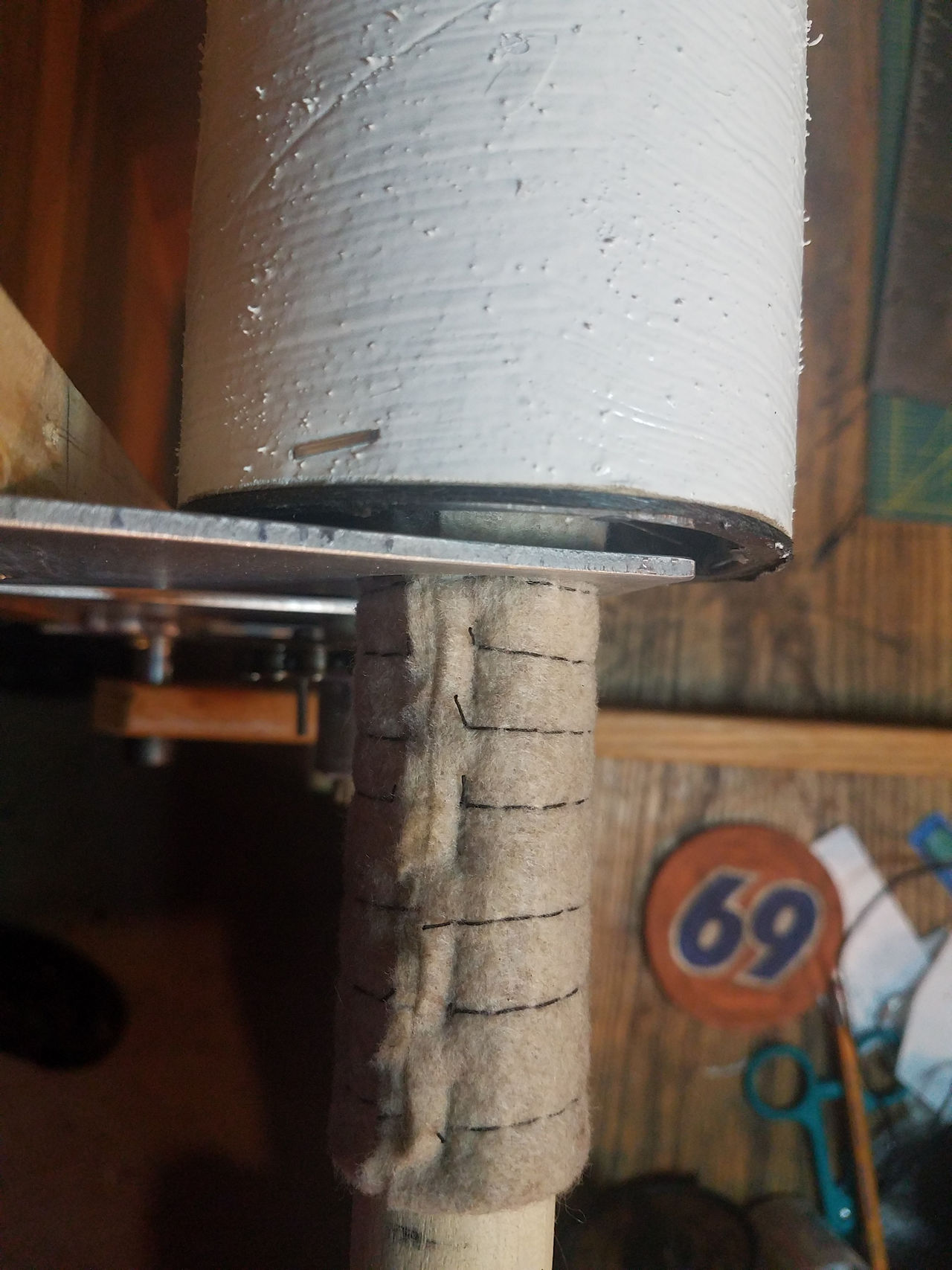 Photo-07: I used felt for the bushings on the roller wooden rods. I stitched two layers together and attached them directly to the wooden rods with 20 gauge 1/4 inch wide crown staples. I also attached the end-caps to the spindles with a 20 gauge 3/8 inch wide crown staple. |
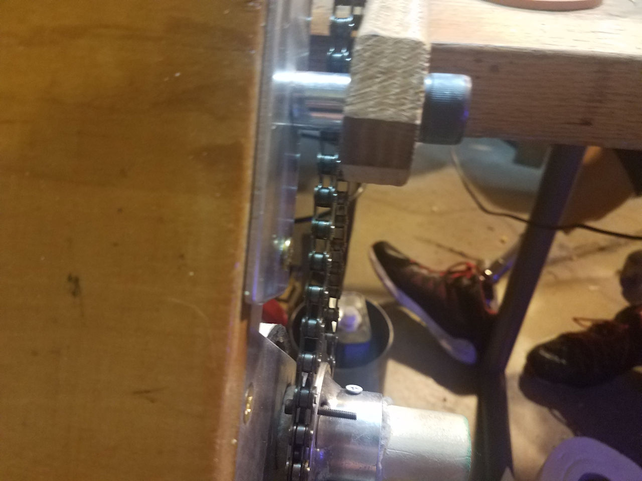 Photo-08: a close up of the initial fitting of the chain clearance between the table mounting brace and arm turned out to be a little narrow for a 1 inch spacer. I'll add a half inch section to this later. |
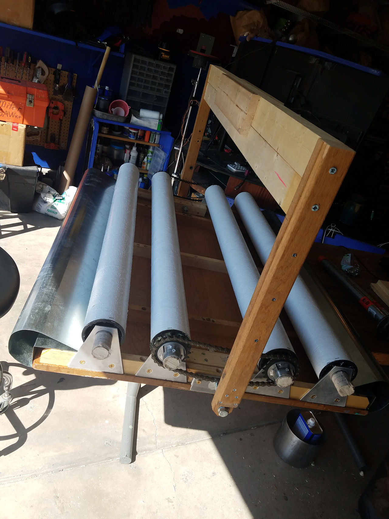 Photo-09: I originally made the mounting arms quite long, but decided to shorten then after trying this length out. It was just too long to support the table way out there on two arms. |
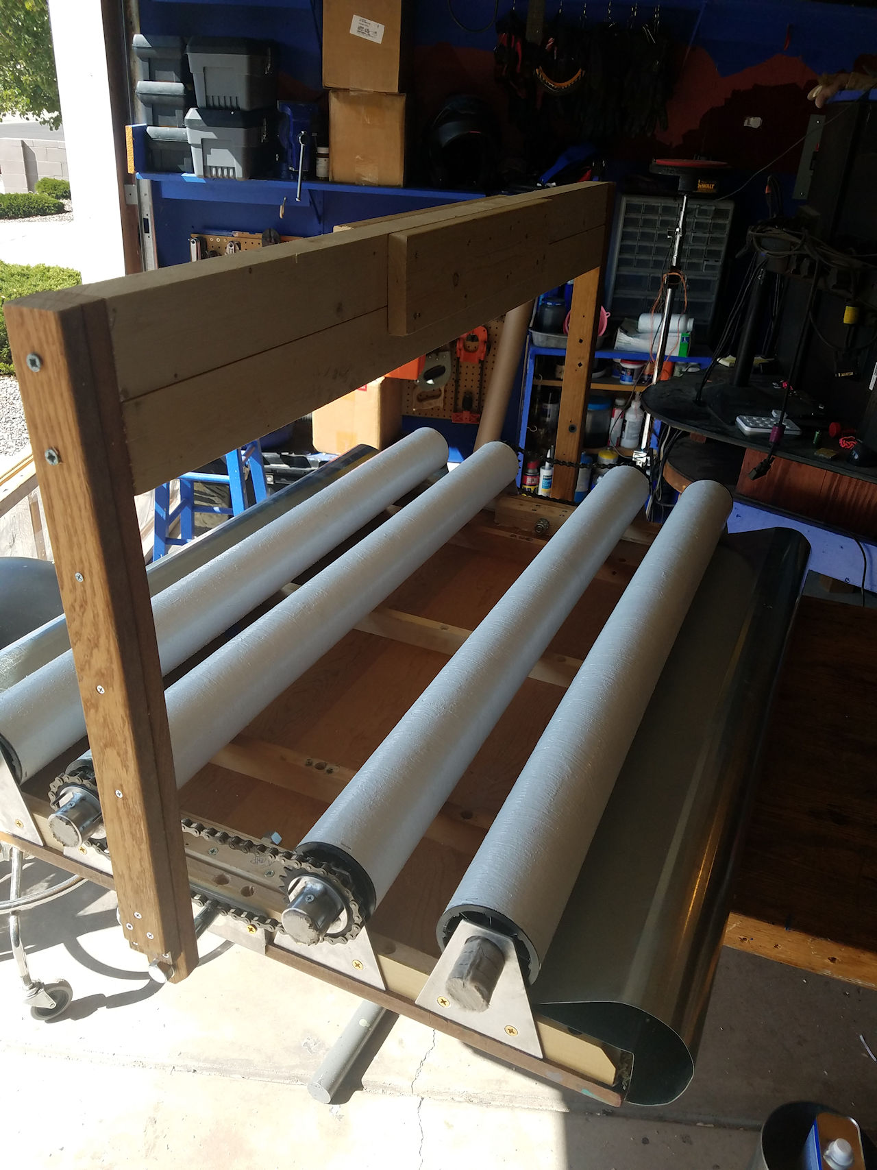 Photo-10: the end caps are on and the rollers all assembled. the clear marine vinyl is not yet on. |
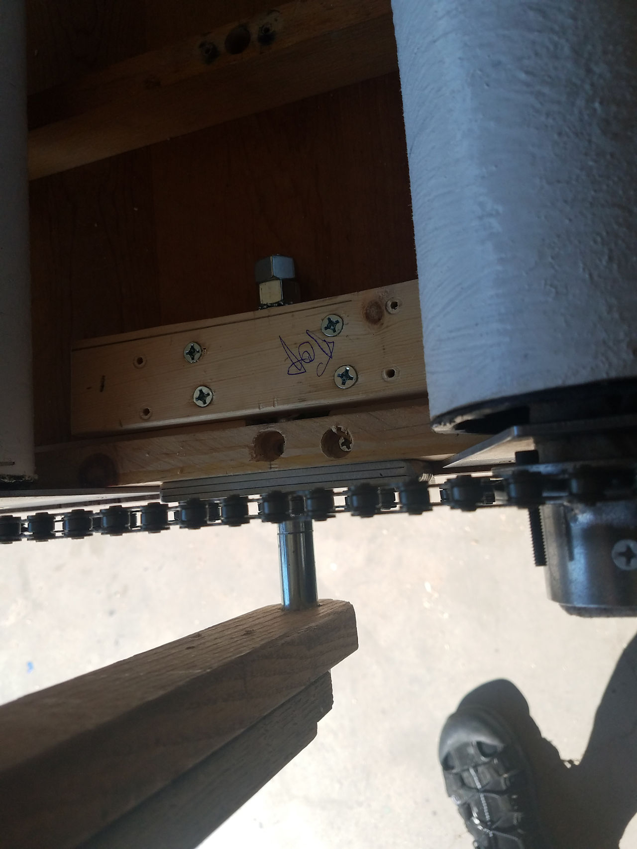 Photo-11: A close up of the connection for the support brace arm to the table. A 7 inch long 5/8 inch steel bolt is on both sides of the table and passes through the aluminum table side bracket and wooden brace as well as a 1.5 inch piece of wood secured to the table. The Wood block has a 1 inch steel sleeve inside that the bolt passes through. |
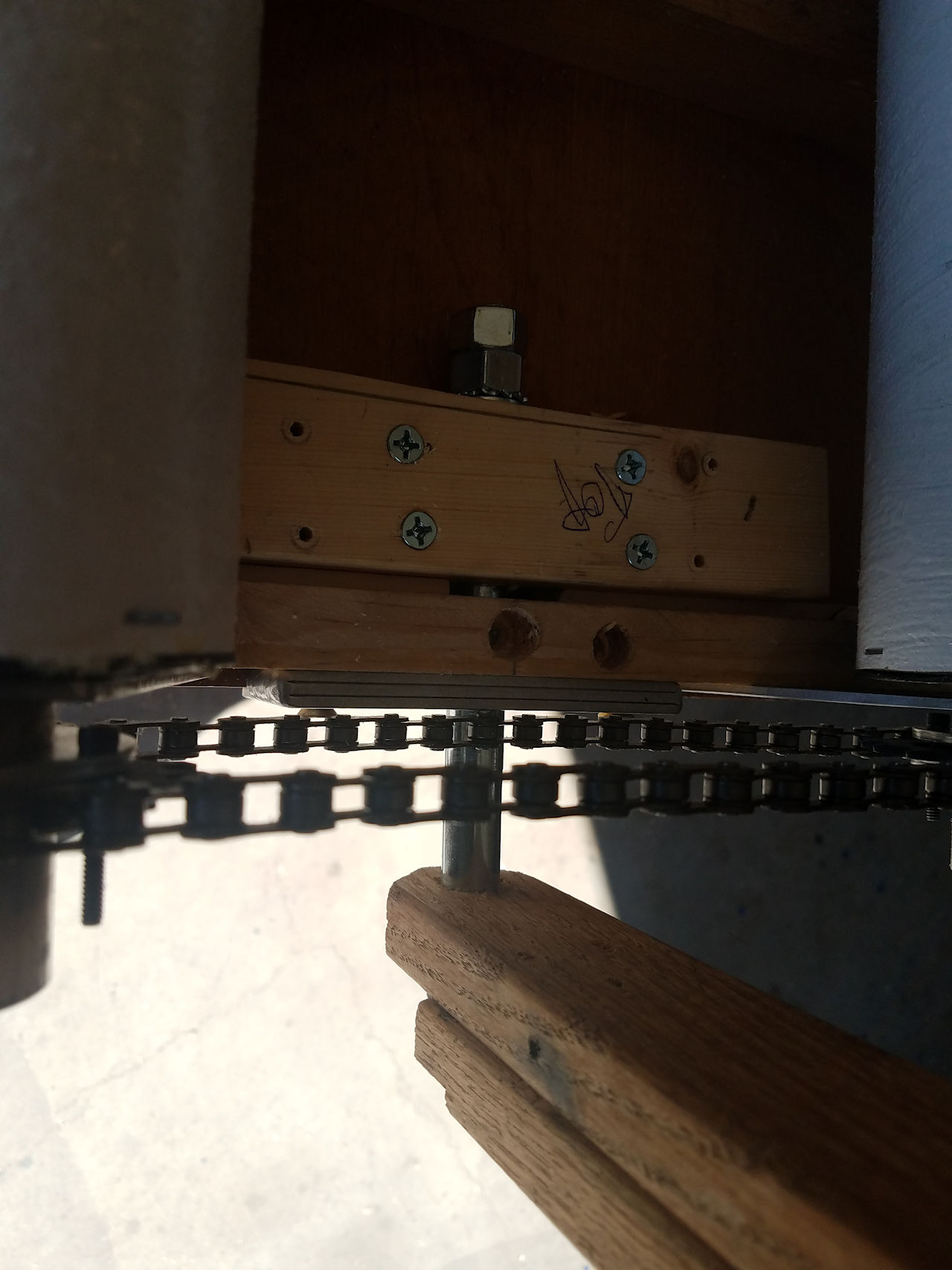 Photo-12: The stand off mounting arm is about 1 3/8 inches. about 1/4 inch hole is drilled in the wooden arm brace for the sleeve to recess into. I also beefed up the arm by adding another oak board to it. They are left over from the original table frame. |
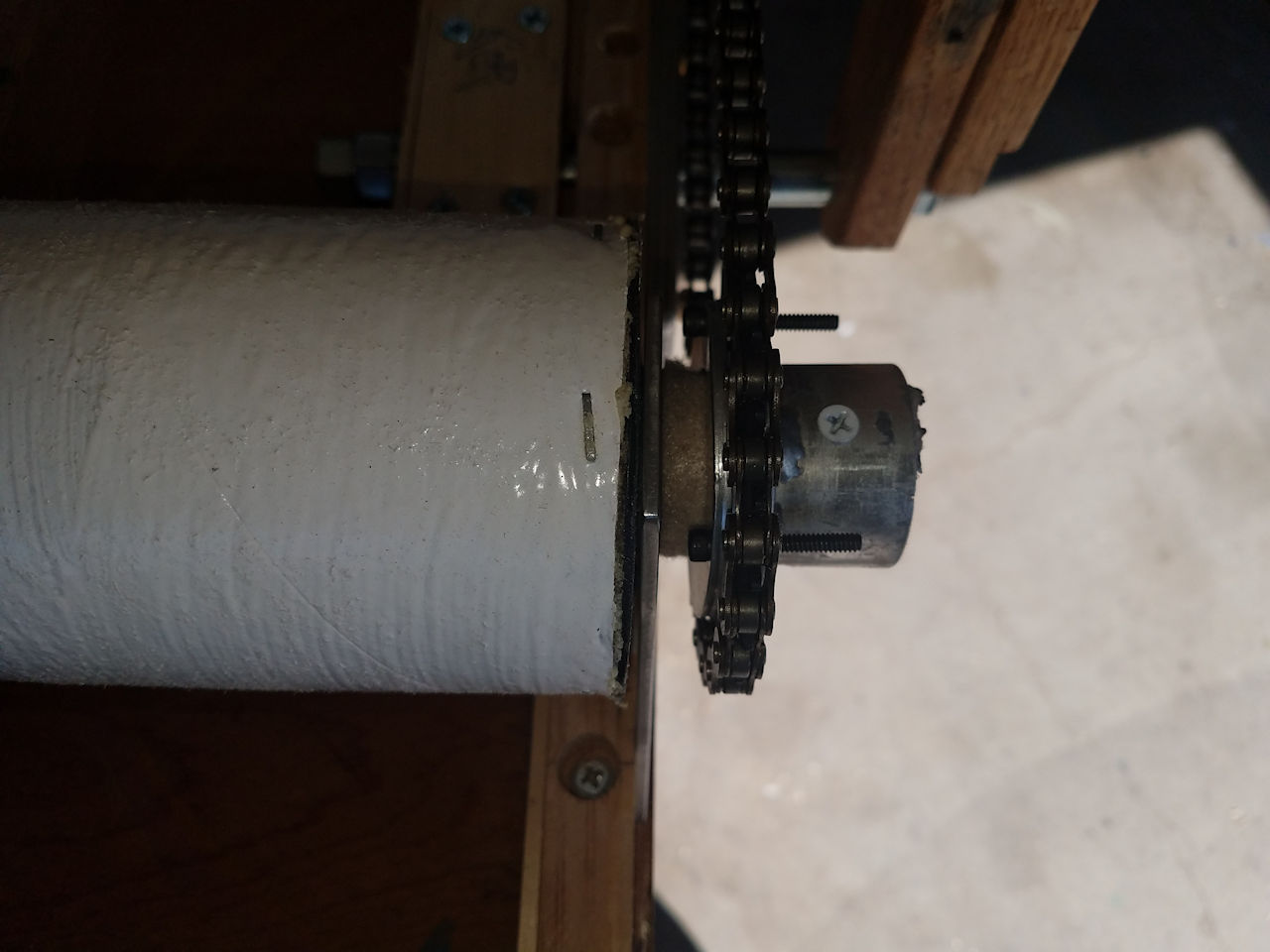 Photo-13: The vinyl can be easily pulled up or down without a crank handle. So, I cut off all the wooden rods to the same length and even with the end of the sprocket assembly. |
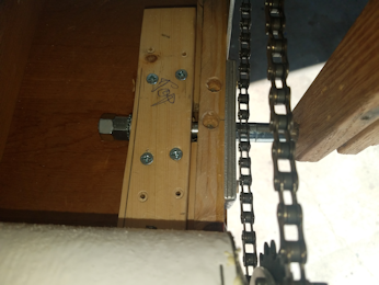 Photo-14: Another close up of the table and arm attachment. item from outside to inside are as follows. one 7" steel 5/8" bolt, set (steel washer, nylon washer, steel washer), Oak Arm brace, one 1" & one ½" steel sleeve, metal mounting bracket, wood table brace, set (steel washer, nylon washer, steel washer), lock washer, two nuts. |
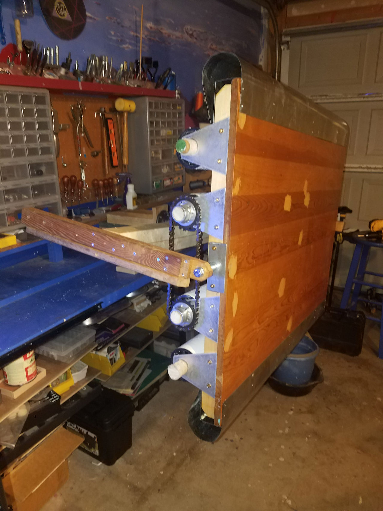 Photo-15: Mounting test to work bench. Arms are now made from three oak boards, which I haven't cut to final length yet. The cross brace is pine. |
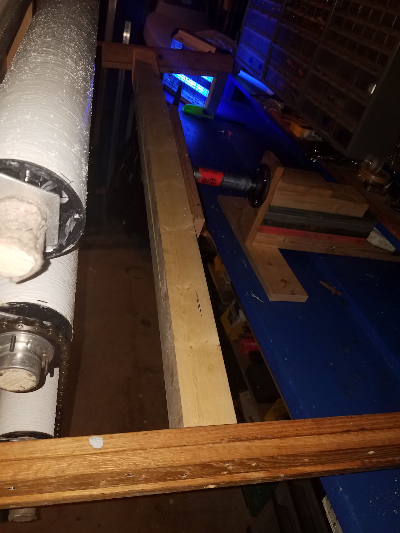 Photo-16: Mounted Table. Arms still aren't cut to final length. |
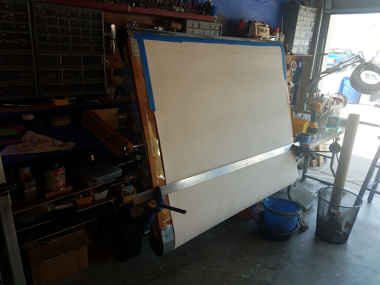 Photo-17: The vinyl is attached to the spindles and the art paper is attached to the vinyl. I got 3 yards of the vinyl so I have about 66.5 inches of article canvas that moves up and down the table. |
A 5/16" hole on the top of the outside pipe will be tapped for a hex head bolt. This tightens against the inside pipe to secure it in place. I thought about adding drill notches around the inside pipe so it can be locked into specific degrees. I'm holding off on that for the meantime, till I see how the single bolt works. Large screws secure the workbench mount to the workbench. |
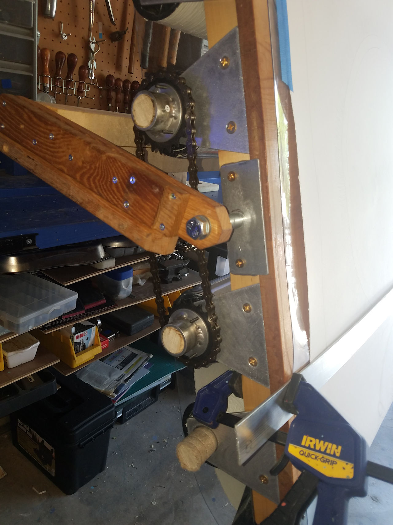 Photo-19: A close up of the mounted table with paper on it. I have a metal bar that I clamp to the side to provide a clean spot to rest my hand when drawing. |
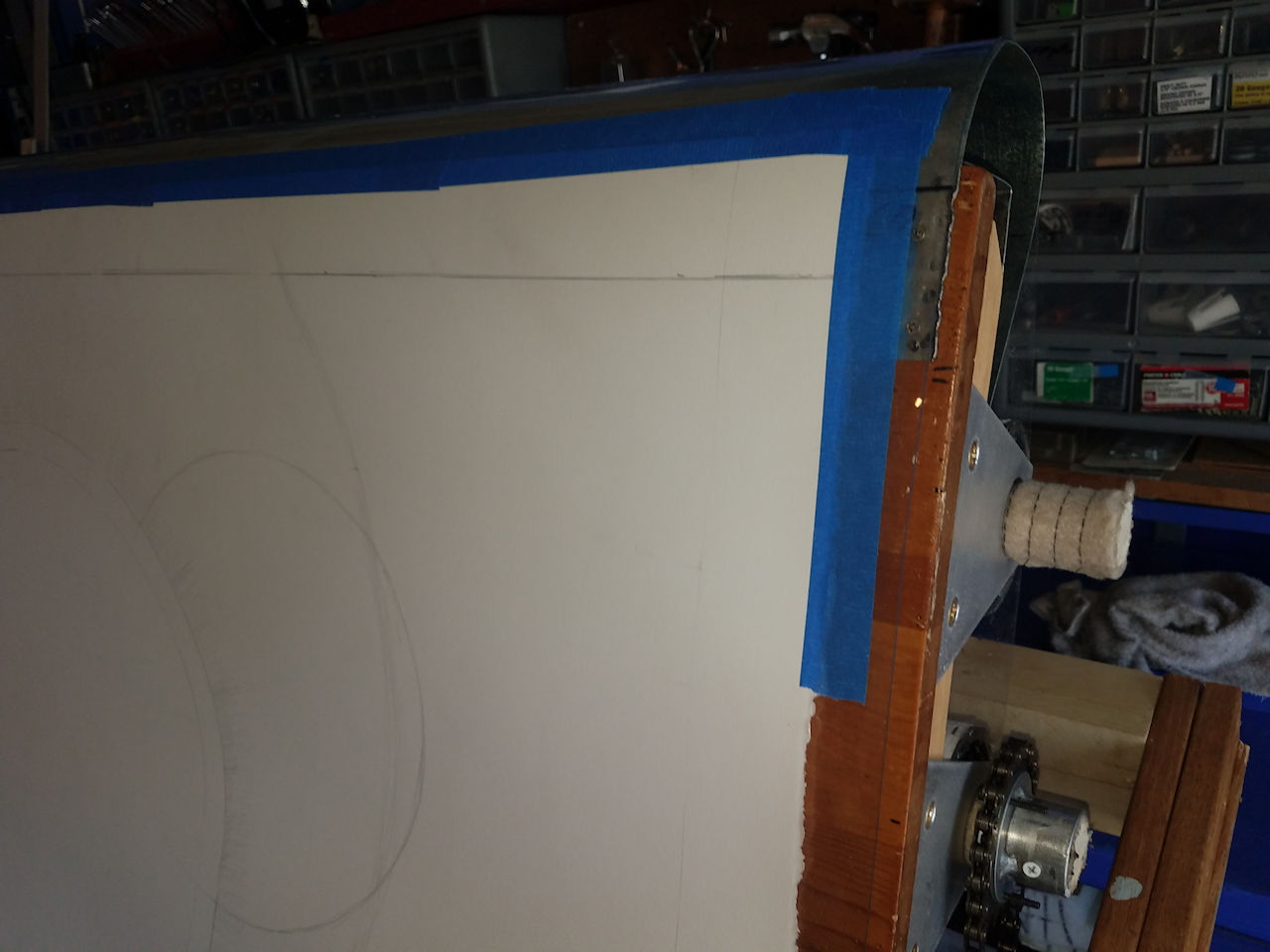 Photo-20: The paper is taped to the clear vinyl at the top and the bottom. |
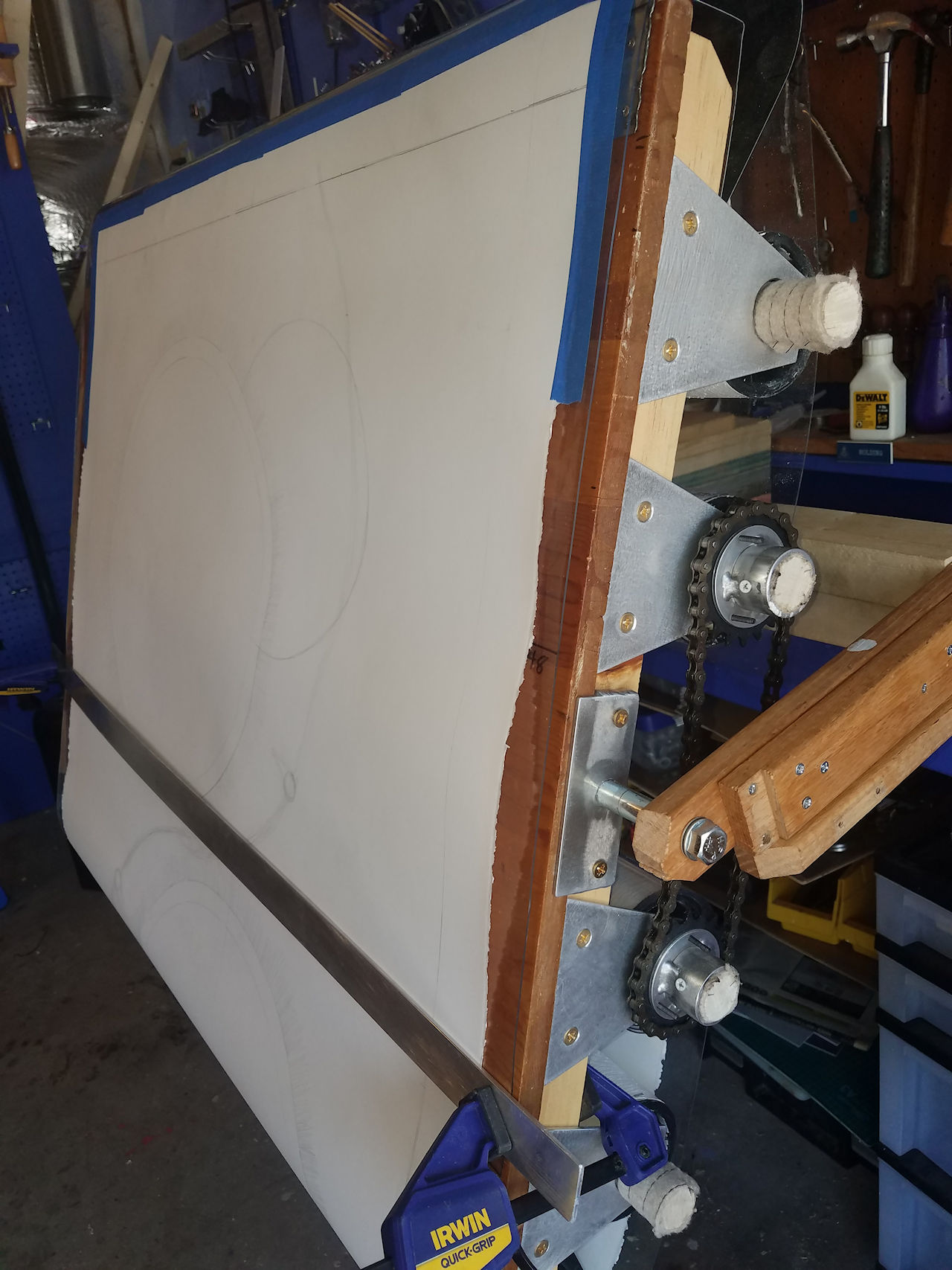 Photo-21: A view of the side with everything ready to go. Photo-21: A view of the side with everything ready to go. |
|
 Photo-23: They did an excellent job. The ends tapered down to a flat bar for attachment to the table. |
 Photo-24: the pipe fitting is cast iron, so he filled the holes with welds to lock it to the brace. Perfectly centered too! |
 Photo-25: The steel brace used square tubing. It made a very nice brace and support the table and me leaning on it. |
 Photo-26: I remade the mounting block for the workbench to hold the brace. The bolts go all the way through the workbench with large washers to hold it down. |
 Photo-27: View of the brace mounted to the table side. |
 Photo-28: AJ working on piece. |
 Photo-28: AJ working on piece. |
 Photo-30: All wrapped up and ready for storage. |